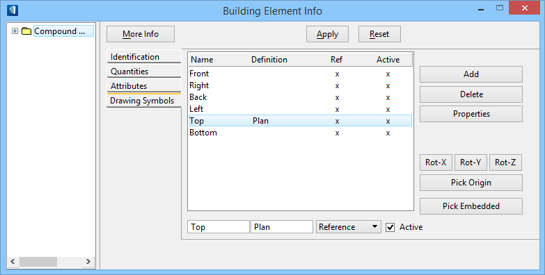
| Drawing Symbols list box |
- Name — Displays the name of the drawing symbol. The value can be edited in the field found below the column.
- Definition — Displays the definition of the drawing symbol. Values can be edited in the fields below the list box.
- Ref — An "X" populates this column if the drawing symbol is stored in a cell library and not in the compound cell. A reference to that cell is made by placing the cell name here. When the drawing is extracted, the cell is retrieved from the library and placed in the drawing. To operate properly, the cell library must be attached and available to the model.
- Active — An "X "populates this column if the item appears in the extracted drawing. More than one view can be active and each view appears in the drawing if the orientation is planar to the cut. Turn this setting on and off using the Active check box at the bottom of the dialog.
|
| Drawing Symbols list box fields and toggles |
- Name field — Sets the drawing symbol name.
- Definition field — Sets the drawing symbol definition.
- Reference — Sets the drawing symbol as a reference symbol or an embedded symbol.
- Active check box — When on, the specific drawing symbol is active.
|
| Add |
Click to view other orientations for the compound cell. Click Add to determine the Front, Right, Back, Left, Top, and Bottom orientations for the compound cell in extracted drawings. Enter user-defined names for the orientation by clicking Add more than once. |
| Delete |
Deletes the drawing symbol orientation from the list. Deleted items do not appear in the extracted drawing. |
| Properties |
Opens the Drawing Symbol Properties dialog where Active, Visible, and Double Sided properties are toggled on and off. |
| Rot-X, Rot-Y, Rot-Z |
Click to rotate the selected drawing symbol, in the model, about the axis. |
| Pick Origin |
Click to select a new origin for the drawing symbol in the model. |
| Pick Embedded |
Select graphic element(s) to define the embedded portion of the drawing symbol for the currently selected orientation. |